In the world of high-precision manufacturing, your machine talks to you. For operators of Double Disc Grinders and Clamp Bore Face Grinding Machines, a change in the “hum” of the shop floor is often the first warning sign that tolerances are at risk.
At C&B Machinery, we know that the spindle is the heart of your operation. Whether you are holding tight flatness on a double disc grinder or critical perpendicularity on a clamp bore application, spindle health is non-negotiable.
Here is a guide to understanding what that new noise means and how to troubleshoot it before it becomes a catastrophic failure.
Common Causes of Spindle Noise in Grinding Machines
Noise is rarely random. In heavy-duty grinding applications, it usually points to specific mechanical distress signals.
1. Bearing Failure & Preload Loss
The immense pressure required for face grinding, especially in double disc applications where “head settings” (tilt and opening) are critical, puts significant load on spindle bearings.
The Sound: A grinding, growling, or high-pitched squeal.
The Cause: Normal wear is expected, but premature noise often indicates that the bearing preload has been lost or the raceways are damaged. In Clamp Bore machines, where squareness to the bore is key, even minor bearing wear can quickly throw parts out of tolerance.
2. Lubrication & Coolant Contamination
Your grinding environment is wet and aggressive. While our machines are built to withstand this, seals can eventually wear.
The Issue: If coolant bypasses the labyrinth seals or the spindle boot, it washes away grease or mixes with grease/oil.
The Check: Look at your grease. If it has a “milky” consistency, coolant has contaminated the bearing housing. This turns lubrication into a sludge that generates heat and noise rather than reducing friction.
3. The “Hidden” Culprits: Rotary Unions & Outboard Supports
Sometimes the noise isn’t coming from the main spindle bearings at all.
Rotary Unions (Deublin): Many of our machines utilize through-spindle coolant. A failing rotary union can cause excessive vibration and a chattering noise that mimics a spindle failure.
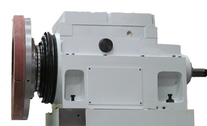
Outboard Bearing Supports: On belt-driven spindles, the outboard support often takes the brunt of the belt tension. If this support fails, it transmits noise through the shaft, sounding exactly like a catastrophic spindle crash.
4. Spindle Bellows & Boots
In Double Disc grinding, the abrasive swarf is relentless. Rubber spindle boots/bellows are your first line of defense.
The Cause: A simple crack or tear in a rubber boot allows swarf to pack into the slide ways or spindle housing. This can cause a “crunching” sound during in-feed or oscillation.
Troubleshooting Tips: A C&B Checklist
Before you tear down a machine, perform these non-invasive checks to isolate the issue.
1. The “Rotary Union” Test
If your machine uses a rotary union for coolant and you hear vibration or chatter, remove the union temporarily and run the spindle “dry” (without grinding). If the noise vanishes, you’ve saved yourself a spindle rebuild, replace the union and get back to work.
2. Visual Boot Inspection
Inspect the rubber spindle boots on your Double Disc grinders daily. Look for cracks, tears, or holes. If you find one, assume contamination has occurred.
3. Check the Grease Consistency
Inspect lubrication ports. If you see water or milky grease, the seals have been compromised. Do not just add more grease; the contamination must be flushed, which often requires a teardown.
4. Measure Deflection
Place an indicator on the spindle nose and apply force. Excessive deflection or backlash typically confirms that the internal bearings have lost their preload and a rebuild is necessary.
The C&B Spindle Rebuild Solution
When troubleshooting confirms a spindle issue, “good enough” repairs won’t hold the tolerances C&B machines are famous for.
Our Spindle Rebuild Service is designed to bring your equipment back to OEM specifications. We don’t just swap bearings; we revitalize the precision of your machine.
Our Process:
Teardown & Clean: We completely disassemble the spindle head assembly in a clean environment.
Root Cause Analysis: We don’t just fix it; we tell you why it failed (e.g., coolant ingress, crash impact, fatigue).
Precision Reassembly: Using OEM-specified bearings, seals, and spacers.
Balancing & Testing: Every rebuild is run on our in-house test stand to monitor temperature, vibration, and noise levels before it ever leaves our floor.
Hearing something unexpected on your line?
Don’t wait for the crash. Contact C&B Machinery’s service department today to schedule an evaluation or spindle rebuild.
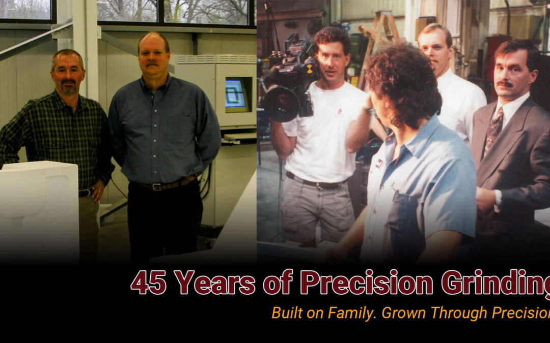
In the world of manufacturing, every part tells a story. At C&B Machinery, our story begins not with machines, but with people.
Back in 1980, our founder Joe Parker set out on his own with a toolbox, a vision, and two little girls at home. He named the company after them, Courtney and Brooke, a daily reminder of why hard work and perseverance matter. Joe started small, refurbishing grinding machines one job at a time. What he didn’t know then was that this hands-on work would give C&B a foundation unlike any other: a deep, practical understanding of what makes grinding machines reliable, durable, and built to last.
Fast forward 45 years, and we’ve grown into a trusted name in precision grinding solutions. From our home in New Hudson, Michigan, we’ve expanded from rebuilding legacy machines to designing and building new, state-of-the-art equipment. Along the way, we’ve partnered with some of the world’s largest manufacturers, and we’ve kept the same focus that guided Joe at the very beginning: solving problems, supporting customers, and standing behind every machine we put our name on.
What makes C&B different isn’t just the technology, it’s the people behind it. Our team takes pride in combining decades of hands-on experience with the drive to innovate. Whether we’re breathing new life into a 50-year-old grinder or designing a brand-new system, our goal is simple: give our customers the confidence that their production line will run with accuracy, efficiency, and peace of mind.
Through all the changes in manufacturing, one thing hasn’t shifted. C&B Machinery is still a family-minded company at heart, committed to building relationships that last as long as our machines.
We’re excited to share our journey here on LinkedIn, stories of innovation, lessons learned on the shop floor, and the values that continue to guide us.
👉 Follow Us to learn more about how we’re shaping the future of precision grinding, one customer at a time!
C&B Machinery is proud to announce the award of three major projects across the automotive and aerospace sectors. These wins further demonstrate our leadership in delivering precision grinding solutions for high-performance manufacturing environments.
Project #1: Automotive Transmission Program
Vertical Clamp Bore Face Grinders for Automotive Program
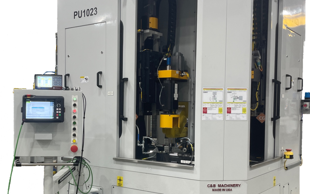
C&B has been chosen by one of our leading automotive customers to design and build six (6) new dual-spindle vertical clamp bore face grinding machines. These orders will replace competitor machines delivering our latest machine design with a flexible Fanuc robot automation solution!
C&B CBVR Clamp Bore Face Grinder
Project #2: Aerospace Braking System Components
Horizontal Park & Grind Double Disc for Aerospace Program
C&B has also secured an order with a Tier 1 aerospace supplier of airline braking system components. Supplying one of our specialized Park & Grind horizontal double disc grinding machines for large round parts. This equipment will support demanding production requirements and reflects C&B’s continued growth in the aerospace sector, where precision and performance are critical.
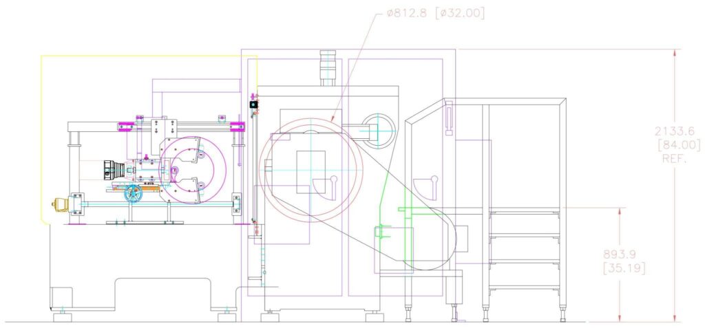
C&B Park & Grind Double Disc Drawing
Project #3: Automotive Tier 1 Parts Supplier
Horizontal Thru-Feed Double Disc for Engine Components
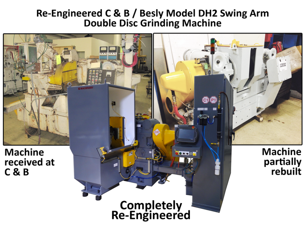
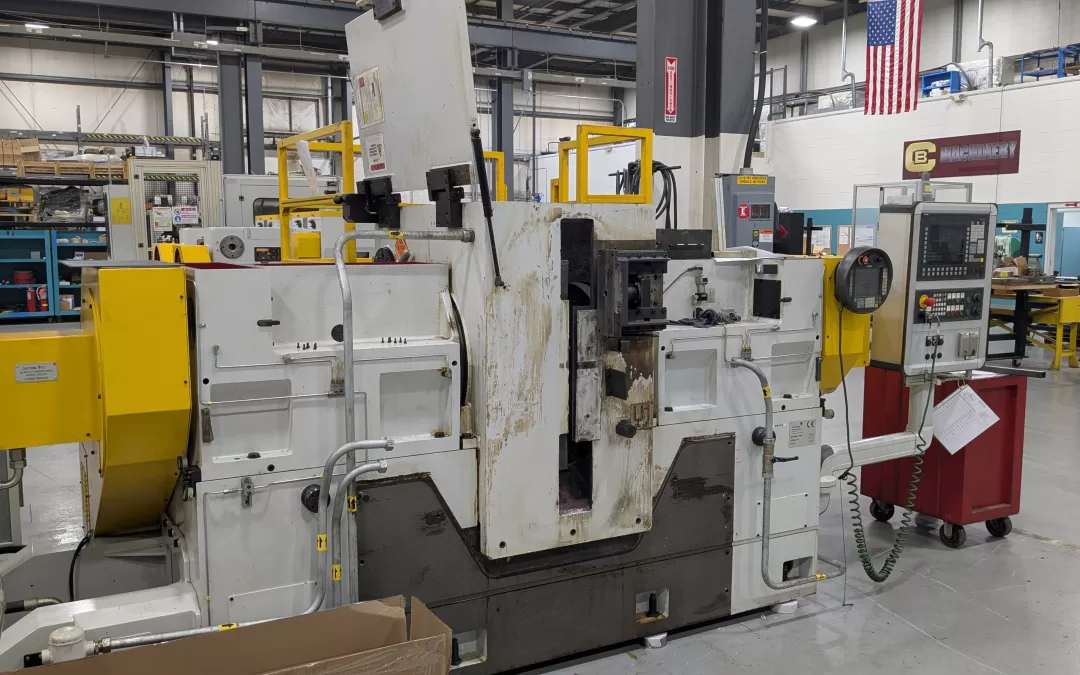
Finally, C&B has been awarded a mechanical and electrical retrofit of a customer-supplied Besly through-feed horizontal double disc grinder. The rebuild will restore the machine to like-new condition with modernized controls, updated components, and enhanced reliability extending the value and lifespan of this customer’s existing asset while increasing production capabilities.
C&B Rebuilt Besly Grinding Machine
These recent orders highlight C&B Machinery’s commitment to delivering custom tailored solutions that improve production efficiency, accuracy, repeatability, and the long-term value for our diverse customer base across all sectors.
Contact Us today to learn how C&B Machinery can support your production needs now and into the future!
The core goal of alignment is to ensure the grinding spindles, the dressing mechanism, and the part tooling/guides are all precisely positioned relative to each other. This ensures accurate grinding and consistent part quality. The process generally involves these key stages:
Machine Leveling: Before any alignment, the machine base must be perfectly level and stable, ensuring all leveling points have equal bearing. This provides a foundation for all subsequent alignments. Different machine styles (like C&B/Besly vs. Gardner) have specific leveling procedures and points to check.
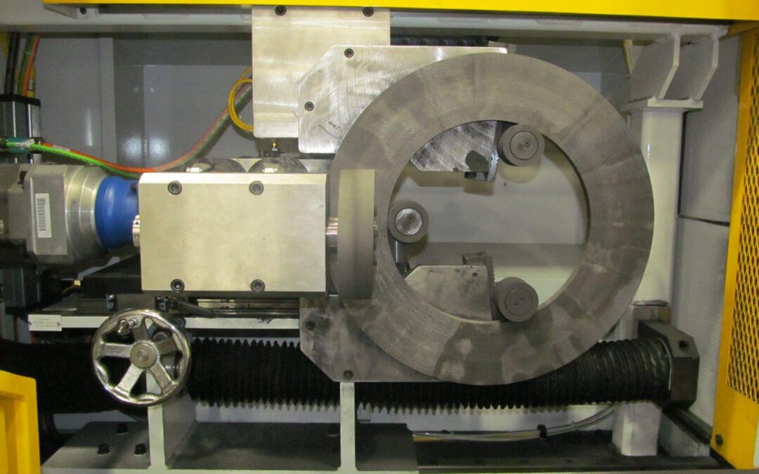
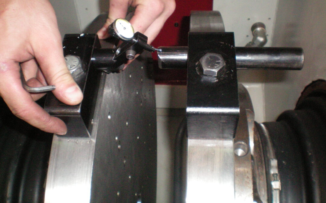
Spindle Alignment (“Zeroing”): This critical step ensures the two opposing grinding spindles are perfectly parallel and coaxial (aligned on the same axis). This is often called a “6-point alignment”. It typically involves mounting special indicator blocks with backing plates on the spindles and using dial indicators to measure and adjust the spindle heads until they read zero deviation across multiple points (top/bottom, front/back). The adjustment method varies depending on the machine design (e.g., pivoting head vs. pivoting quill). Spindle alignment should generally only be done if spindles have been disturbed or if other troubleshooting fails.
Dresser Alignment: Once the spindles are zeroed, the dresser arm (which holds the diamond tool to true the grinding wheels) must be aligned parallel to one of the spindle faces (typically the left-hand one). This ensures the dresser creates a flat, true face on the grinding wheel that is perfectly parallel to the spindle’s axis. This involves mounting an indicator to the dresser arm and sweeping it across the aligned spindle’s backing plate, adjusting the dresser shaft mounting until the indicator reads zero deviation. Tool-mounted dressers align inherently with the tooling.
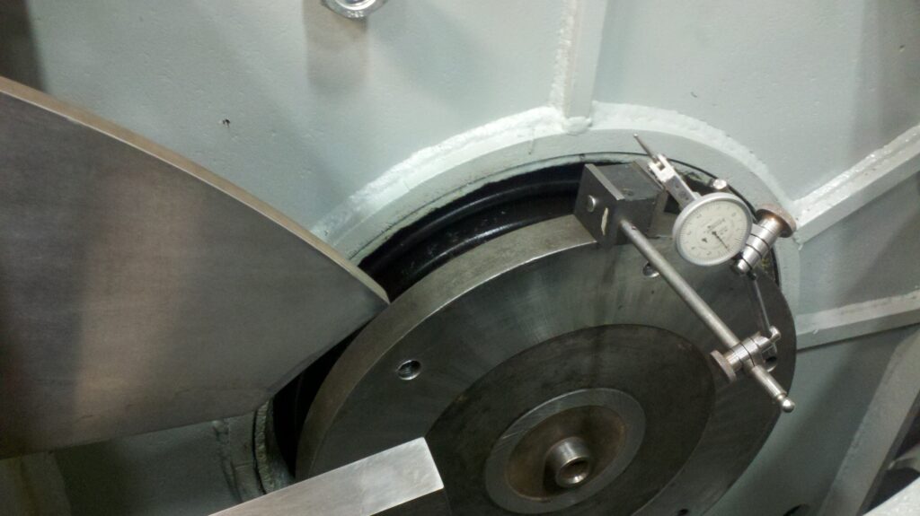
Tooling and Guide Indication: After the spindles and dresser are aligned, the part-holding tooling (like rotary carriers, swing arm blades, and paddle fixtures) and the entrance/exit guides must be aligned parallel to the spindle faces (again, typically the left-hand spindle). This ensures parts are presented correctly to the grinding wheels and guided properly through the grind zone. The method depends on the tooling type (carrier, swing arm, progressive, plunge) but generally involves using indicators mounted on the aligned spindle or straight edges to check and adjust the tooling’s position relative to the spindle face. Entrance guides should center the part, and exit guides should have clearance so they don’t influence the finished part.
Double Disc Guide Indication
Once these core alignments (Leveling, Spindle, Dresser, Tooling) are set to “zero,” specific “Head Settings” (slight tilts or openings) might be applied depending on the grinding method (shear vs. plunge) and tooling type to optimize stock removal and part quality.
Need Expert Assistance?
While this guide covers common troubleshooting steps, every grinding application has unique variables. Sometimes, persistent or complex issues require deeper expertise.
If you’re facing ongoing challenges with part quality or want to optimize your double disc grinding process further, the specialists at C&B Machinery are here to help. With decades of experience in disc grinding solutions, we can provide tailored support, service, and process development assistance.
Upgrading a 30” Double Disc Grinding Machine for a Major U.S. Automotive Manufacturer
C&B Machinery is proud to support the reshoring of a 30” Double Disc Grinding Machine for a major U.S. automotive manufacturer’s transmission plant. Originally installed in an overseas facility, this machine is now being brought back to the U.S., where it will be retooled, reautomated, and upgraded to enhance performance and efficiency for a Michigan-based production program.
Key Upgrades and Enhancements:
✅ Automatic Gaging System – The machine will be upgrade with a closed-looped gaging system to ensure precise, post-process measurements and improved quality control throughout the grinding process.
✅ Fanuc Robot Integration – We are replacing the existing complex automation system with a streamlined, standardized Fanuc robot, improving efficiency, reliability, and compatibility with the customer’s existing automation setup. This upgrade ensures a common automation platform across their plant, simplifying maintenance and operations.
✅ Updated Pump Back System – The machine will feature a redesigned pump back system, significantly reducing its overall footprint and saving valuable floor space in the facility while maintaining optimal coolant and swarf management.
✅ Flexible & Standardized Tooling – To enhance flexibility, the machine is being retooled to accommodate the manufacturer’s entire part family, utilizing common tooling already in use within this facility. This standardization reduces changeover times and increases production efficiency while aligning with the customer’s existing processes.
By implementing these upgrades, C&B Machinery is ensuring that this reshored grinding machine will not only meet the demands of the current production environment but also provide long-term value in efficiency, automation, and precision grinding.
We’re excited to see this machine back in action, supporting the expansion of U.S.-based automotive manufacturing! For more information, contact us today to learn how C&B Machinery can support your production needs.
C&B Machinery (C&B) announced the completion of their newly redesigned Clamp Bore Face Grinding Machines. After months of planning, redesigning, and building the machines, C&B is excited to announce the latest CBVR-2F-2S model Clamp Bore Grinders.
Clamp bore face grinding machines are specifically designed for generating tighter squareness/perpendicularity tolerances for high-precision face grinding applications.
After numerous discussions, brainstorming sessions, and conversations with our customers, C&B embarked on the challenge of updating the design of their Clamp Bore Face Grinding Machine. The process took about a year with multiple redesigns throughout the process. Collaboration between Sales, Engineering, and Service Engineers helped achieve the final design.
FEATURES AND BENEFITS:
An ideal fit for tighter tolerances required for EV Drive Gears.
Overall Simplified Design
Reduced Cycle Time
Reduced Price
Reduced Downtime
Reduced Spare Parts
Reduced Swarf Buildup
Easier Access for Maintenance
We Consider Our Customers Our Partners
When asked about redesigning the C&B Clamp Bore Face Grinding Machine, President of C&B Machinery, Bill Tulpa, said the following:
Listening to our customers was the main push for us, but we also listened to our Service Engineers. We consider our customers our partners. We want honest feedback from them. They live with our machinery every day. We asked them what improvements would help them the most with uptime, maintenance, and overall production. We took the feedback from our customers and our Service Engineers and made the necessary improvements. I don’t think our newly designed Clamp Bore could have turned out better. It was truly a team effort!
Jeff Allen, Vice President of Operations, added:
The idea of implementing a robot into the clamp bore grinding machine has been getting bounced around for years. We facilitated numerous brainstorming sessions and discussions. The kind of brainstorming where you wake up in the middle of the night with an idea. That was the excitement around this redesign.
We also put a lot of weight on specific customer feedback and requests based on existing customers using older model clamp bore face grinding machines. There were specific requests on what design changes they would like to see on the new model.
The previous design of the C&B Clamp Bore Face Grinding Machine had a gantry system that made servicing the machine a challenge and required a high number of spare parts.
Standard clamp bore face grinding machine design included a gantry system that required a large number of parts. All of these parts were located within the interior of the machine, making servicing the machines difficult, as the space to work was very tight. The C&B Engineering Team worked to improve our work holding tooling and remove the gantry to achieve the desired upgrades. Allen provided details about the design:
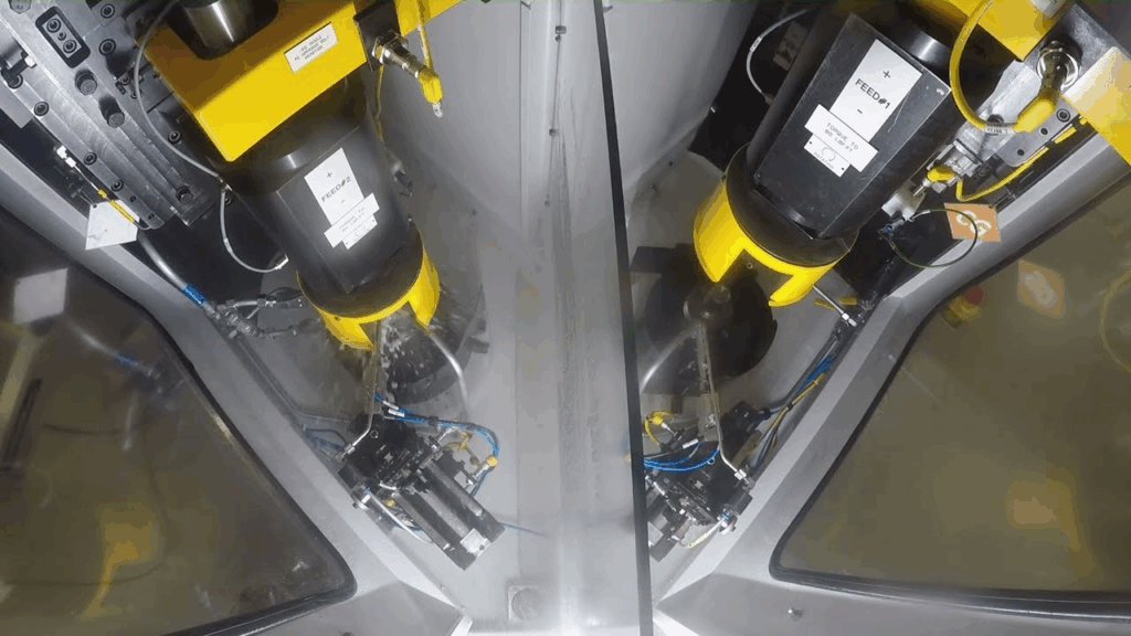
The core components of the machine stayed the same. We repositioned the spindle columns to replace the gantry mechanism. This one change allowed for several previous components to be removed, making the machine more open and maintenance-friendly. The main change is that we have incorporated a Fanuc robot within the machine for the movement of parts.
The part handling area of the machine is simpler than in previous models. This is an area where many of our service calls occurred. The new design fixes the issue before it happens.
After testing multiple design concepts, the new design will be put into production in the very near future and multiple machines are being manufactured. This machine design allows users easier access to the spindles, gauges, and work holding than previous models. It also provides better coolant flow and minimizes areas for swarf buildup.