The core goal of alignment is to ensure the grinding spindles, the dressing mechanism, and the part tooling/guides are all precisely positioned relative to each other. This ensures accurate grinding and consistent part quality. The process generally involves these key stages:
- Machine Leveling: Before any alignment, the machine base must be perfectly level and stable, ensuring all leveling points have equal bearing. This provides a foundation for all subsequent alignments. Different machine styles (like C&B/Besly vs. Gardner) have specific leveling procedures and points to check.
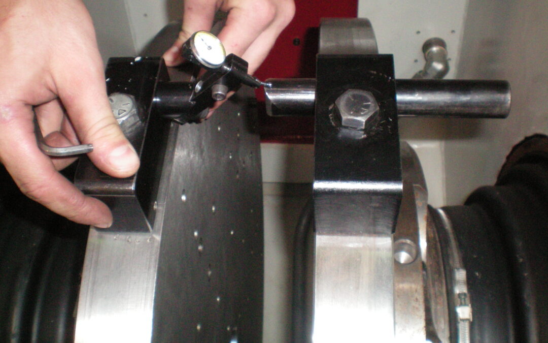
- Spindle Alignment (“Zeroing”): This critical step ensures the two opposing grinding spindles are perfectly parallel and coaxial (aligned on the same axis). This is often called a “6-point alignment”. It typically involves mounting special indicator blocks with backing plates on the spindles and using dial indicators to measure and adjust the spindle heads until they read zero deviation across multiple points (top/bottom, front/back). The adjustment method varies depending on the machine design (e.g., pivoting head vs. pivoting quill). Spindle alignment should generally only be done if spindles have been disturbed or if other troubleshooting fails.
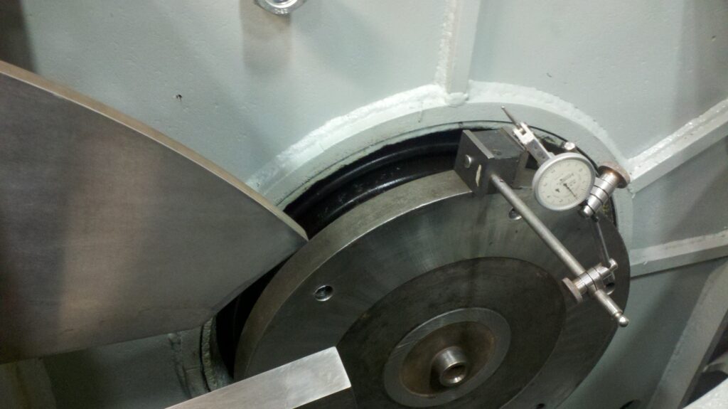
- Dresser Alignment: Once the spindles are zeroed, the dresser arm (which holds the diamond tool to true the grinding wheels) must be aligned parallel to one of the spindle faces (typically the left-hand one). This ensures the dresser creates a flat, true face on the grinding wheel that is perfectly parallel to the spindle’s axis. This involves mounting an indicator to the dresser arm and sweeping it across the aligned spindle’s backing plate, adjusting the dresser shaft mounting until the indicator reads zero deviation. Tool-mounted dressers align inherently with the tooling.
- Tooling and Guide Indication: After the spindles and dresser are aligned, the part-holding tooling (like rotary carriers, swing arm blades, and paddle fixtures) and the entrance/exit guides must be aligned parallel to the spindle faces (again, typically the left-hand spindle). This ensures parts are presented correctly to the grinding wheels and guided properly through the grind zone. The method depends on the tooling type (carrier, swing arm, progressive, plunge) but generally involves using indicators mounted on the aligned spindle or straight edges to check and adjust the tooling’s position relative to the spindle face. Entrance guides should center the part, and exit guides should have clearance so they don’t influence the finished part.
Once these core alignments (Leveling, Spindle, Dresser, Tooling) are set to “zero,” specific “Head Settings” (slight tilts or openings) might be applied depending on the grinding method (shear vs. plunge) and tooling type to optimize stock removal and part quality.
Need Expert Assistance?
While this guide covers common troubleshooting steps, every grinding application has unique variables. Sometimes, persistent or complex issues require deeper expertise.
If you’re facing ongoing challenges with part quality or want to optimize your double disc grinding process further, the specialists at C&B Machinery are here to help. With decades of experience in disc grinding solutions, we can provide tailored support, service, and process development assistance.
Contact Us Today!
Phone: +1 248.264.9800
Email: sales@cbmachinery.com
Website:www.cbmachinery.com